Sunday, April 20, 2014

Interfacing Vixen 3.0.10 to the Raspberry Pi DMX utility.


 Interfacing Vixen 3.0.10 to the Raspberry Pi DMX utility.


This article covers getting Vixen 3.0.10 [BETA] working with the DMX utility. Vixen supports E1.31, which is a standard network protocol for talking to DMX devices. Using E1.31 we can have Vixen running on a different system than the Raspberry Pi. This way the Raspberry can act as a DMX server, while any system can send packets to it.

I’m not a Vixen expert. The below details the steps I took to get Vixen to talk to the DMX Utility. The setup is Vixen running on a PC running Windows (I’ve tried with both 8 and 7) and the DMX utility running on a Raspberry Pi. (The Pi is running Raspian 3.10 (wheezy)) I’m using the wireless network on the Pi. (Which doesn’t appear to have any latency issues when receiving UDP packets – which is what the E1.31 spec calls out).

The DMX utility needs to be started with the --e131 and/or the --e131m option. (see the “start here” link)


On vixen, select the “Setup Display option in the “System Configuration” box.


Next we’ll add our “Elements” (Lights). The lights I’m using are LED RGB each consuming 3 channels, one each for Red, Green and Blue. I select “Single Item” and then press the green button. (The “+” one).


I name my elements L1 through the L5 (I’ve a small installation). Let’s start off with L1.


We need to configure the Color Handling, so we select “Color Handling” from the drop down and click the “Configure” (cog) icon.


Select “They can be any color”. Once you click “OK”.


You should see the amount of Patch Points go up to 3.


Once all 5 elements have been configured, you should have this on the left hand side of the screen. (Five RGB Lights/elements – each using 3 channels.)


Now we need to set up the controller and link the lights to channels on the controller. On the right hand side of the screen we select “E1.31 Output Controller” from the dropdown list and click the green button. We can name our controller anything. I’ve named it “DmxPi”. We really on need 3x5=15 channels, but I’ve created 20 output count, as that’s what the DMX utility defaults to.


 Now we select each element from the left and a group (using the Ctrl-Key) of outputs on the left and “patch” the elements together by pressing the “Patch Elements to Controller” button. You need to patch L1 to #1, #2 and #3 and L2 to #4, #5 and #6, etc…


We need to configure the controller for Universe, where it starts and how big it is. Press the “Configure” cog on the bottom right of the screen. You will see the “Setup Form”. If you’re using Unicast (using the - - e131 option on the DMX utility) then you need to set the destination as the IP of your Raspberry Pi. This is a two-step process. First, right click on the destination dropdown, a box asking for the IP will immediately appear. Type in the IP address of your Pi and click “OK”. Next, select the Unicast option from the Destination dropdown. (Which will now be populated). If you’re using multicast (using the –e131m option on the DMX utility) then select the Multicast network that your Pi is on. (ie, wireless, or Local Area if you’re hooked in to the lan). Select the universe that you’re in. One is probably the best default. If you set it to something else, then use the –universe option on the DMX utility to ensure that both ends match). Set the size of the universe to 20 (again, I’m only using 15 channels). Don’t forget to check “Act” to activate the address. I set the Max Repeat and Max Suppress count to 3, so that there’s not a lot of noise on the network, but during debug/set up, you may want to leave these are zero. Click OK and then OK on the Setup Display page, and now you can start a “New Sequence”. (Read the Vixen docs on what to do here)


Thursday, April 17, 2014

DMX - Connecting your DMX device.


Connecting your DMX device.


Most DMX devices have an “XLR” type connector, some have RJ45, but they’ll all have a D+ and a D- pin. (Note that this doesn’t mean the same as positive(+) and negative(-) voltage, it’s to do with the “differential”, in this case, if the voltage on D+ is higher than the voltage on D-, that’s a logical 1, if D- is higher than D+ it’s a logical 0.)

For a three pin XLR, pin 2 is the D+ while pin 3 is D-. We don’t need to worry about ground for transmitting data.


For my generic RS485 dongle, the connectors are unhelpfully labeled “A” and “B”. A is D+ and B is D-. To connect the RS485 dongle to the DMX device you’ll need to use a twisted pair cable. This isn’t a special cable, you can make your own (I did). If you wrap a standard wire around a post/door knob/whatever, you can then stick the loose ends in a drill, pull the cable tight and drill-baby-drill your own twisted pair cable. (drill slowly, too fast and you’ll end up not twisting the cable evenly). 


Not a very good diagram – but you get the idea – I hope. Alternatively, buy some twisted pair or use CAT5e (Ethernet).

For our set up, we connect “A” to pin 2 and “B” to pin 3. Hopefully whatever DMX device you’ve bought has enough documentation to let you know which pins/cables to connect.

If you’re connecting multiple devices, then you’ll use twisted pair between them all, and you’ll be connected daisy chaining them all. (ie, pin2 to pin2 and pin3 to pin3 on each device).


The DMX spec calls out for a 120 ohm terminating resistor. If you’re connecting to one device over a short length, then you’ll probably not need the terminating resistor. I’d advise getting a collection of resistors in the 100 ohm range, as I’ve found that a lot of issues can be solved by using a terminating resistor. You put the resistor between pins 2 and 3 in the last device in the link.

DMX on the Raspberry Pi - Start Here.


DMX on a Raspberry Pi

When you get a Raspberry Pi, you want to do something cool, unique and very Pi-ish. This project has some of that. You can use much of the project on any Linux system, but I do make use of the PiFace for turning power on/off and the project allows you to create a very low cost DMX controller.
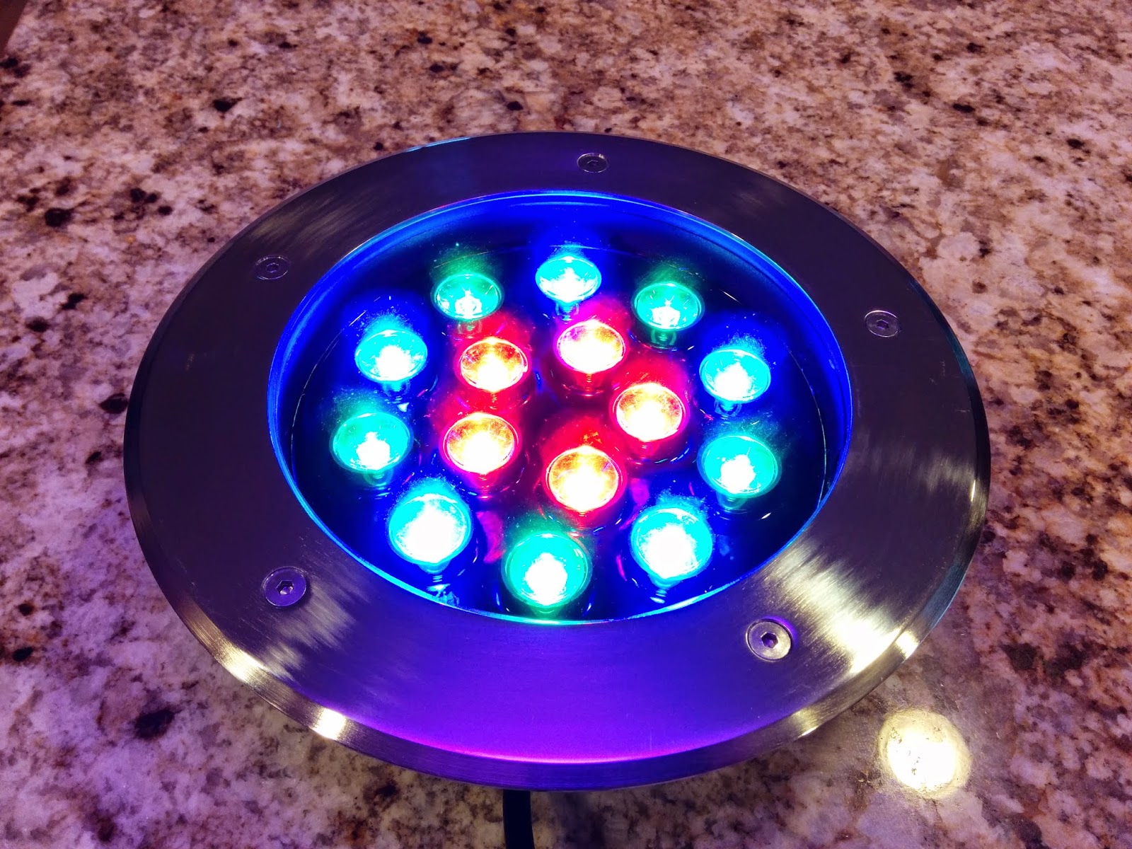
DMX LED Light
Firstly, what is DMX? DMX is used for controlling lights in stage and concert productions, it’s also used for controlling lots of other things, in my case the, the lights in my back garden/yard. These are DMX LED lights that you can buy online and I’m sure from all good lighting stores. (Although I don’t know of any).


My Trees rocking out to Enya. They don't know any better.

DMX uses RS485 for its hardware/signaling. Most people are familiar with RS232, a serial communication relying essentially on three wires (TX, RX and GND). RS485 uses a single twisted pair (two wires wrapped around each other) that is great for a one-to-many communication.  On top of the RS485 is the DMX data protocol which provides up to 512 bytes of information per packet. Each packet is made up of a start sequence (a BREAK followed by sending a ZERO byte) and then one or more bytes of information called “channels”. Each channel controls a “dimmer” – that can have a value from 0 (off) to 255 (fully on). Typically a DMX device will consume a number of channels. For example my lights have red, green and blue LEDs so consume three channels, one for each color.

To get DMX running on a Raspberry Pi, you’ll need a RS485 device. A USB-to-RS485 device runs about $10. This example uses a generic converter which contains the “Widely-supported” Prolific PL2303.
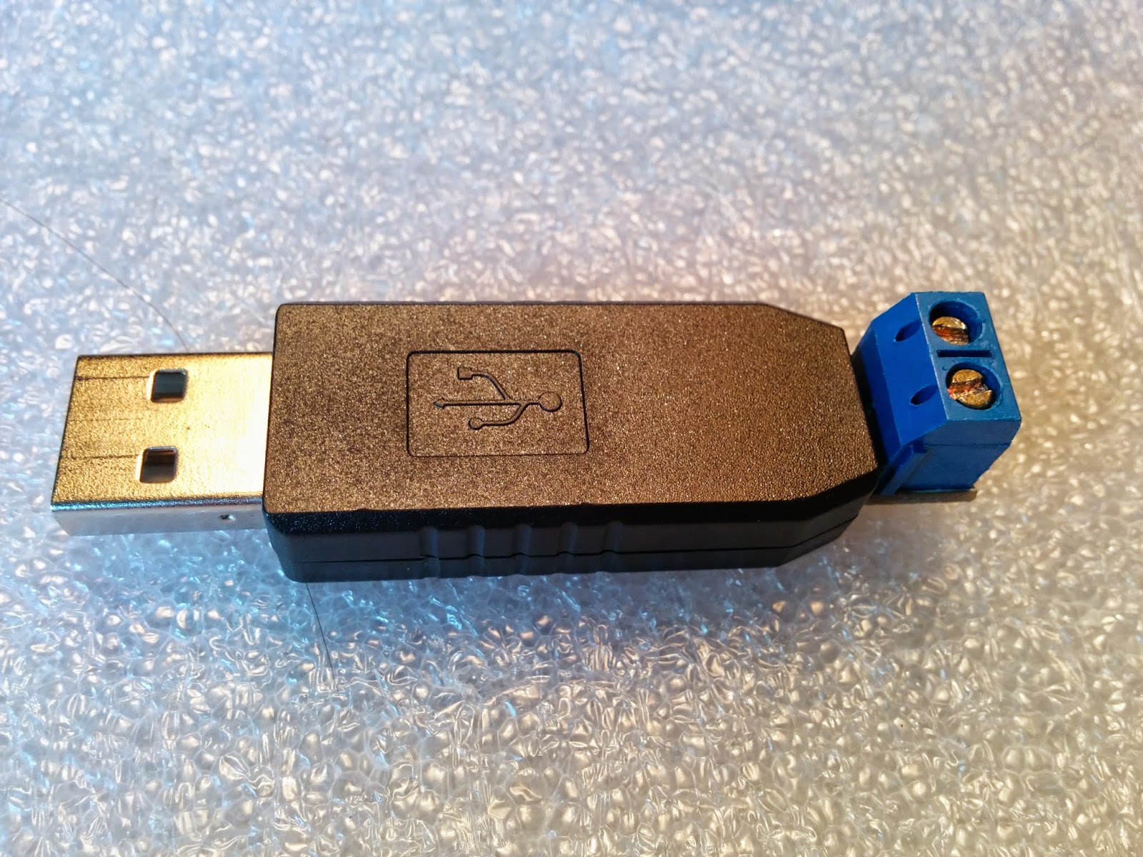
My USB adapter is so generic; it’s probably covered by your healthcare plan.

Note that the driver and utility are based on the 3.10 version of rapsbian (wheezy).

cat /proc/version

Linux version 3.10.25+ (dc4@dc4-arm-01) (gcc version 4.7.2 20120731 (prerelease) (crosstool-NG linaro-1.13.1+bzr2458 - Linaro GCC 2012.08) ) #622 PREEMPT Fri Jan 3 18:41:00 GMT 2014

The Modified USB Serial Driver.

The modified driver is needed to support the DMX baud rate. It’s the standard USB-PL2303 driver with one BAUD rate change to support 250,000 Baud. For details on modifying your driver (if you don’t want/can’t use the pre-built driver, read this.)

The DMX utility.

The DMX utility talks to the serial port (/dev/ttyUSB0 by default) sending DMX packets out to whoever will listen. (Hopefully some DMX lights)

To see all the options, use

                dmx –h 

This will show the following:


DMX User Space Driver version n.n

--break, user standard BREAK

--mab=n set MARK after BREAK value (microseconds)

--mbs=n, set delay between channels (microseconds)

--mbb=n, set delay after packet (microseconds)

--init=n, starting value for channels, deafult is zero

--channels=n, set the count of channels to transmit,default is 20

--starttype=n, value for first byte sent

--device=<device>, serial device to use, default is /dev/ttyUSB0

--e131, enable unicast e1.31 network support

--e131m, enable multicast e1.31 network support


--universe, multicast universe, default is one

--help, show help

Here’s a review of the options:

BREAK, this tells DMX to use standard “Linux sized” breaks. The start of each DMX packet has a BREAK. The standard Linux BREAK is much longer than required, so there’s some jiggery-pokery to get around this. If you’re having problems talking to your DMX lights, you may want to enable ‘break’ to use the standard BREAK.

MAB, “MARK after BREAK”, how much to delay between the BREAK at the start of the packet and sending the first bytes. The default is 12 microseconds, which is what the spec says.

MBS, “MARK between slices/bytes”, how much to delay after each byte is sent. The default is zero, which means that it’ll send a complete stream of bytes. If you specify a value, then there’s a delay after each byte has been sent.

MBB, “MARK before BREAK”, how much to delay between each packet. The default is zero, but DMX does ensure that the previous packet has been sent before starting a new packet.

INIT, the initial starting value for the DMX channels. The default is zero, which means everything should start OFF. If you want to have everything starting on – and startling everyone, then use 255.

CHANNELS, how many channels to send. The DMX protocol allows up to 512. If you don’t have that many devices you should limit this. DMX defaults to 20. Note that the fewer channels that are sent the more packets that can be sent each second.

STARTTYPE, the first byte in the packet is typically a zero. Some devices can key off other start types. You’ll probably want to leave this at zero unless you know what you’re doing.

DEVICE, this points to the serial device to use. This defaults to /dev/ttyUSB0, which is the usual name assigned to the USB serial (RS485) device. If you have a few serial USB devices, the name may change.

E131, enable unicast (sending to a specific IP) support. The DMX utility will receive E1.31 network packets and send to the DMX devices.

E131m, enable multicast support. The DMX utility will receive E1.31 network packets and send to the DMX devices.

UNIVERSE, this selects the universe that multicast will listen to. The default is one.

Note that dmx is (to some extent) a user space driver, to make it operate in a similar way to a driver, it uses names pipes to get/send information.  (Ultimately, I’d like to make it a driver, but for now it’s easier to work it (and build it) as a utility.

Installation.

Download the driver here:

Download the DMX utility here:

(coming soon, once I clean it up, Download source here)

First, install the driver. We need to uninstall the current driver (If loaded), make a backup, copy the new driver into place and install the new driver. As stated above, the driver is based on the 3.10 version of rapsbian (wheezy). The current driver on your system will be here:

                /lib/modules/3.10.25+/kernel/drivers/usb/serial

The steps:


1.       Make sure you’re super user
a.       sudo  su

2.       Get to driver land
a.       cd  /lib/modules/3.10.25+/kernel/drivers/usb/serial

3.       If you have the USB-RS485 device installed, remove the driver.
a.       rmmod  pl2303

4.       back up the current driver
a.       cp  pl2303.ko  pl2303.ko.works

5.       copy the downloaded driver into place
a.       cp  /<download location> /pl2303.ko   .

6.       load the module

a.       insmod  pl2303.ko

7.       Create the named pipes and set some viable permissions.
a.       mkdir  /var/dmx
b.      mkfifo  /var/dmx/dmxin
c.       mkfifo  /var/dmx/dmxout
d.      chmod  777 /var/dmx/dmxin

8.       copy the utility into place
a.       cp  /<download location>/dmx   /usr/local/sbin

9.       Launch DMX in background with the defaults
a.       dmx &

Now DMX should be happily running away, you should be able to talk to it by sending “commands” to /var/dmx/dmxin. The basic command is channel#:Value. Channel is from 1 to 512 and Value is 0 to 255.

                 Set channel 1 to 50:

                                 echo  1:50  >/var/dmx/dmxin

                set channels 3,4 & 7 to 40

                                echo  4:40 4:40 7:40  >/var/dmx/dmxin

                 get the current values for all the channels

                                echo 0:1  >/var/dmx/dmxin
                                cat  </var/dmx/dmxout

                Instruct dmx to exit:

                                echo  0:0  >/var/dmx/dmxin

Thursday, April 10, 2014

DMX driver for Raspberry Pi - Getting Baud.


DMX on a Raspberry Pi - Getting Baud.

Note the main article is here:

Note that the modifications below are based on the 3.10 version of rapsbian (wheezy).
There are some NOTES for 3.12.

cat /proc/version

Linux version 3.10.25+ (dc4@dc4-arm-01) (gcc version 4.7.2 20120731 (prerelease) (crosstool-NG linaro-1.13.1+bzr2458 - Linaro GCC 2012.08) ) #622 PREEMPT Fri Jan 3 18:41:00 GMT 2014

Baud Rate

The first thing to do is to modify the driver to support the DMX baud rate, which is 250,000 baud. Typically the easiest way to do this is to download the source to the driver and build it. As the standard raspbian image doesn’t contain the files to do this, this can be tricky and you can take up quite a bit of time attempting to set up your environment and even more time attempting to build. (One post states to “go and make some coffee” while waiting. For me it should have said “go build a house”)  The good news is that this inspired me to cheat a bit and patch the driver by hand. This really isn’t recommended, so feel some guilty pleasure when you’re doing this.

A look at the source for the pl2303 driver shows the bauds that are supported.

const int baud_sup[] = { 75, 150, 300, 600, 1200, 1800, 2400, 3600,
                                 4800, 7200, 9600, 14400, 19200, 28800, 38400,
                                 57600, 115200, 230400, 460800, 614400,
                                 921600, 1228800, 2457600, 3000000, 6000000 };


You’ll see that 250000 isn’t one of them. But there is 230400. That’s pretty close. (But not close enough).  The logical thing to do would be to patch that to 250000 and use ‘stty –F /dev/ttyUSB0 250000’ to set the baud. The problem is that Linux (to some extent) has some pre-conceived notions about what allowable baud rates are.

stty -F /dev/ttyUSB0 250000

stty: invalid argument `250000'

 The driver has a section where is will “Set baud rate to nearest supported value”. If we change the “230400” baud to 2500000 and try and set 230400 baud, we actually end up with 115200 baud, which means that the driver is rounding down when it comes to the nearest speed. This means that we need to find a valid baud rate above 250000 that the driver can round down to.

NOTE: The driver for 3.12.22+ has changed/fixed the "nearest supported" algorithm. In order for this patch to work, multiple speed values need to be changed. This is called out below.

The driver is here:
/lib/modules/3.10.25+/kernel/drivers/usb/serial

(or here for 3.12.22+: /lib/modules/3.12.22+/kernel/drivers/usb/serial)

First unload the driver (which will be loaded if you have a pl2303 device installed, such as the USB-RS485 device.)

                rmmod  pl2303

Then make a backup:

                cp  pl2303.ko  pl2303.ko.orig

convert the driver to hex – so you can edit it:

                xxd  pl2303.ko  >pl2303.hex

Now we need to grep for the baud rates. The baud rates that we are looking for are the 230400, 460800 ones (These are from the driver source shown above, I’m not just making numbers up). 230400 = 38400 hex and 460800 = 70800 hex. Let’s grep for that

                cat pl2303.hex |grep 03|grep 84|grep 00|grep 07|grep 08|grep 00

                0001380: 0084 0300 0008 0700 0060 0900 0010 0e00  .........`......

The nice thing is that they’re all on the same line so the grep finds them – if some of the bytes were on the line above/below, then we’d have to grep a bit more cunningly (grep -A1, -B1)

Because of the endian ness of the processor, everything is slightly backwards, but that’s OK. You can see the 00038400 followed by 00070800. You can also see 0096000, which you can see is the 614400 baud rate in the driver.

                echo $(( 0x0096000 ))

So, now we need to edit the driver.

                vi pl2303.hex

                /0001380: (this finds the “0001380” in the hex file – this is from the first part of the grep results above) (NOTE: For 3.12.22+, the location is /00013d0)

Now we need to carefully edit the values. We want to edit the baud rate for 460800  to be 250000.  (that is we need to change the hex  07 08 00 to the hex for 250000 which is 03 D0 90.

Before: 0001380: 0084 0300 0008 0700 0060 0900 0010 0e00  .........`......

The results of your efforts should look like this (based on the line above. If your grep results were different, then your results will differ)

After:    0001380: 0084 0300 90d0 0300 0060 0900 0010 0e00  .........`.....
NOTE: for the 3.12.22+ version, the line needs to look like this:

After: 00013d0: 0084 0300 90d0 0300 90d0 0300 90d0 0300

Now, we need to create the new driver from the hex file.

                xxd -r pl2303.hex >pl2303.ko

load the new module:

                insmod pl2303.ko

                If your system dies spectacularly at this time, then you’ve probably gone astray. You should remove the serial device and reboot your system. Copy the original driver back into place and try again.

                Set the baud rate to 500000, note that the driver doesn’t support this, and will set it to 250000. As 250000 is not understood by linux, you’ll still get an error message:

stty -F /dev/ttyUSB0 500000

stty: /dev/ttyUSB0: unable to perform all requested operations

And even trying to check the speed will not clear things up:

                stty -F /dev/ttyUSB0

speed 0 baud; line = 0;

You’ll have to trust that the baud rate is correct at this time. (or, if you’ve bought two RS485 convertors (and why would you not, these things need friends too) then you can connect it to a Windows laptop and use Putty to connect at 250000, you should be able to “echo HELLO >/dev/ttyUSB0” and see “HELLO” appear on putty.)

So, now you’re able to get to the correct baud, you’re now going to need to send DMX packets to your DMX devices. That’s in the next post.