Showing posts with label DMX. Show all posts

Sunday, June 14, 2020

Rebuilding the USB serial driver to allow for DMX (250000) baud

Rebuilding the USB serial driver to allow for DMX (250000) baud

I wanted to play with a new light and wanted to just use a standard USB serial device. In the past I'd just patched the driver, but that no longer appears possible. (This is a good thing, I was always surprised that used to be able to do this) This meant building the driver. This *should* be simple, but it wasn't. This outlines how to to rebuild the serial driver for Raspbian.

The sequence for building the driver should be simple:
1. Get the source for the driver
2. Get the kernel headers
3. Create a simple Makefile
4. Build
5. Serve

I mainly ran into issues getting the correct headers.

Get the source for the driver

uname -r will tell you the version of the kernel:
  $ uname -r
  4.9.35-v7+

Now you can pull in the source directly from github, updating the version number. Pull in the c file and the header:

  wget https://raw.githubusercontent.com/raspberrypi/linux/rpi-4.9.y/drivers/usb/serial/pl2303.c
  wget https://raw.githubusercontent.com/raspberrypi/linux/rpi-4.9.y/drivers/usb/serial/pl2303.h


Get the kernel headers (Raspbian)

apt install is used to pull in the kernel headers. 

  apt install raspberrypi-kernel-headers

For my installation, the headers getting pulled in didn't match the running kernel. The kernel version was actually quite far ahead. You should ensure that you're up-to-date first

  apt-get update
  apt-get upgrade
  init 6

or in my case:

  apt remove raspberrypi-kernel-headers
  apt-get update
  apt-get install --reinstall raspberrypi-bootloader raspberrypi-kernel
  init 6
Once rebooted:
  apt install raspberrypi-kernel-headers

Check that you have the correct headers. If you have the 'build' directory, then you should be good.

  ls -l /lib/modules/$(uname -r)/build

Create the Makefile

 I'm building pl2303.ko, so all my Makefile needs to contain is:

   obj-m   := pl2303.o

Yes - that's all.

Build

With the headers in place and the Makefile in place, this is all you should have to do to build:

  make -C /lib/modules/$(uname -r)/build M=$PWD modules

Serve

You may need to remove the current module:

  rmmod pl2303

Now you can install your new module:

 insmod pl2303.ko

250000 Baud


The reason for having to build a driver were to be able to set the Baud to 250000 for my DMX device. Linux still has preconceived notions about baud rate, and 250000 isn't one of them, so you'll not be able to easily set the speed you want. I have some existing code (dmx) that sets the baud rate to 500000 with the expectation that the driver will set it to the next closest speed. I used to patch the driver to make this closest (lower) speed to be 250000, but that doesn't work anymore.

       if (baud == 500000) baud=250000;

I added the above line into the driver code - if the baud requested is 500000, then set the baud to 250000. To put this in context:

        /*
         * Use direct method for supported baud rates, otherwise use divisors.
         */
        if (baud == 500000) baud=250000;
        baud_sup = pl2303_get_supported_baud_rate(baud);

        if (baud == baud_sup)
                baud = pl2303_encode_baud_rate_direct(buf, baud);
        else
                baud = pl2303_encode_baud_rate_divisor(buf, baud);

This means that if 500k baud is selected it will change the request to 250k. The 'if ' section (baud_sup) will fail and the baud rate will be set using pl2303_encode_baud_rate_divisor.

That's all.

REF: https://raspberrypi.stackexchange.com/questions/63879/installed-kernel-headers-and-uname-r-differ REF: https://www.youtube.com/watch?v=Zn8mEZXr6nE&list=PL2GL6HVUQAuksbptmKC7X4zruZlIl59is REF: https://www.raspberrypi.org/documentation/raspbian/updating.md


Sunday, May 18, 2014

DMX – The Complete Project.

DMX – The Complete Project.


This outlines the complete (or almost complete) steps for using a Raspberry Pi to control my garden lights. The outside lights use the DMX protocol, so as well as being able to generate different lighting moods; they can also really annoy the neighbors by turning my garden into a disco.

Figure 1: The obligatory picture of the control system

Figure 1 shows the inside of the control box. (I have a control box because my wife really, really, doesn’t like wires – so I have to hide away as much as I can). I’m using a RS485 USB device (around $10, using the Prolific PL2303 chipset), which you can see crammed in the bottom right corner, to control the DMX devices. I’m using the PiFace to turn on/off power to the lights. (I’m also using it to control some LEDs on the front of the control box, but the cables are not connected in the above picture). The big yellow thing on the right shows that I live in America, where twisting wires together is considered a sound connection. I’m using a nano wifi device (the blue light on the left). Also, I had to use a right-angle USB extension (which turned out to be left-angle) to attach the RS485 device, as the box wasn’t long enough. (I could have used a shorter SD card, but I don’t know if they exist)


The above is the basic schematic for the installation. The Raspberry Pi (Blue) is used to drive the RS485 with the DMX protocol. The green box represents the RS485 device, that drives the twisted pair cable that communicates to the lights. At the end of the twisted pair is the terminating resistor of questionable value (see below). The PiFace (Yellow) is used to turn on power to the lights. It also used to drive some of the status LEDs on the front of the control box, but that’s not shown in the schematic. The power supply is a notebook power supply. These tend to provide a lot of power in a small device and are somewhat more consumer friendly than the more industrial power supplies. (Plus, the one i used has a usb port, so I can power the Pi from that.)

Figure 2:  One of these lights

Figure 2 shows one of the lights. I should have put some sort of scale on this, as they’re “Rather Large”. They’re about 12” across. I wanted to light up my trees, so these are 15W RGB lights. Pretty powerful. The lights have four wires (Which in my case, were very well labelled). Two 24V and two DMX, labeled D+ and D-.

Wire turned out to be one of the most expensive parts of the project. I used 200’ of 16 gauge wire for the 24V DC and 200’ of twisted pair cable. I was going to make my own twisted pair, which I’d done during prototyping (using a post and a drill) but I found a reel that was relatively inexpensive. What I should have done was used Ethernet Cat5e cable – not because I needed 4 twisted pairs, but because it’s sooooo much cheaper than just one twisted pair, plus it probably is more durable when buried in the ground, plus, having underground Cat5e in your garden much cooler than, say, owning a Ferrari.

Figure 3: RS485

Figure 3 shows the RS485 device I used. The DMX protocol uses RS485 for the hardware/signaling side of the protocol. On top of that is a relatively simple protocol that uses BREAKs to signal the start of a packet followed by the data. I had to patch the PL2303 driver to support the DMX 250,000 baud rate and write a utility to generate the DMX packets. [Link]  I was waiting for my lights, so I ended up buying a $25 RGB DMX light off Amazon that I could play with. This was quite entertaining, and my daughter was quite amazed to find out that when you mix Red, Green and Blue light you get White. I created a web page so that I could control the lights and then added network support, so that standard DMX software could talk to the Raspberry Pi and control the lights. So far I’ve tested Vixen Lights 3 on my PC and AuroraDMX on my Andriod.

Installing the lights took about a day and a half. Most of the time was spent trenching and burying the cables. I have a ‘Black&Decker’ trencher and edger, so I used that for making the trench. It draws more of a line than actual trenching. I ended up sitting on a kid’s camping chair using paint stirring sticks to push the cables into place, but it worked. The nice thing is that the trencher didn’t get down deep enough to splice pipes or any other cables. The bad news is I don’t know if I’ll be able to aerate my lawn again.


I tested out the installation twice before burying the cable. Once in the house, where I was running into issues and ended up taking 100’ of twisted pair cable and had it going through an assortment of rooms in the house and once in the yard/garden, where I had it laid in position. DMX calls out for a 120 ohm terminating resistor on/after the last device. This is to stop the signal bouncing back. When you have a short run and a few devices, you’ll not need this, but once you get a long line of cable, it becomes an issue. When I did the test runs, I needed a larger resistor, around 150 ohms. Luckily I had these to hand. Once I buried the cables, this no longer worked. The lights I have go into an automatic mode when they’re not getting any commands, so it was pretty obvious that something was wrong.  Initially I thought that it was a loose cable and had the annoying experience of finding and fixing the loose cable only find out that it wasn’t the real issue. I ended up trying an assortment of resistors in different configurations until something worked. In my case, two 150 ohm resistors in parallel, so 75 ohms. Next time I think I’ll invest in a variable resistor/rheostat/potentiometer and use that to find out the correct resistance, and then connect up the right amount of resistance.

The reason for the 120 ohm resistor is based on the impedance of the cable. Obviously there’s some dark magic at hand that I don’t quite understand. maybe cables are like people, they put up less resistance when buried underground.


With the cable trenched, I installed the lights. I dug holes just slightly larger than the lights and filled it in with dry concrete. (I had to redo the lights a few weeks later, as while the lights had plenty of bedding, they didn’t have a whole lot of encasement on the side, so I dug a wider hole and filled that in with dry concrete. The rain took care of the rest). I was initially going to use a garden type control box for each junction, but in the end use some underground spicing devices, some electrical tape spray and wrapped it up in plastic – this appears to be working, but I’ll have to see how long they last.

With the lights installed and the testing complete, it was time to drill a hole in the side of the house and fish the cables through to the control box. I used the PiFace to control the power to the lights. The positive wire is connected to the “common” connection on relay#2 and the line to the lights is connected to the “open” side of the relay. (The side that’s not connected to common by default, you can see the lose screws in the picture above).  Note that the PiFace spec calls out 20 volts or 5 amps max, I’m 24v at about 3 amps, so I think I’m OK. (you can see in the picture above that the relays can cope with more. I assume the limitation is based in the traces on the PCB) It appears that all the PiFace documentation points you to perl.  I use the gpio utility, which can be slightly odd (“gpio –p write 200 1” sets the top relay on, but you need to use “gpio –p read 209” to read the current state of the relay).

The nitty-gritty inside the Raspberry Pi is difficult to take a picture of, so here’s a written version. I’ve modified /etc/rc.local to run the utilities that I need when the system boots up.

/usr/local/sbin/dmx -e &
/root/lights/lights.sh >/var/log/lights.log &

The /usr/local/sbin/dmx is the utility I created to talk the DMX protocol to the RS485 device. I’ve documented this in a separate blog/blogs. [link]. The ‘-e’ option enables E1.31 unicast network support.
The “lights.sh” is a shell script that is split into three parts. The first part calculates the amount of seconds until sunset and sleeps until sunset (garden lights being a more nocturnal activity). The second part turns the lights on and generates a random set of values for the lights. The third part shuts the lights down when it gets late.

Figure 4: Unimpressive Web Frontend

The webpage controls the power to the lights as well as the lights themselves. It’s quite unimpressive as I wanted to use the “slide” type (for reasons that currently escape me – I think to avoid huge wads of java script ). There’s some java script, mainly communicating to PHP scripts on the server that do the actual control of the lights and turning the relay on/off.  Really I should have a front end where you just select the color of the light you want (well, that’s what my wife wants).

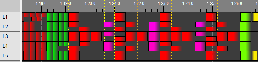
Figure 5: Vixen pumping up my lights

As well as certain “staged” or set scenes for lights, you may want to pump up the jam/jelly. Figure 5 shows my take on the middle bridge(?) on “Hello”. I’m no expert on any DMX mixing/lighting software. I tend to learn how to use software by banging my head against it for a while and then giving up and reading the manual. In the case of DMXcontol and FreeStyler, they both look great but I didn’t make it over the first hurdle. I then took a look at Vixen.


Vixen appears to be the choice of people who want to overdo it on Christmas lights. I liked it because it kind of fit in with how I imagined DMX software would work. It has a timeline and you can plonk different effects on each light and it has a nice “Preview” that works. It also support “E1.31 Output Controller”, which is a pretty generic way of talking to lights over the network, so I updated the DMX utility to understand E1.31 and was able to make my lights sing and dance. (Link to setting up Vixen for use with theDMX utility). I’ve banged my head against it for a while, but I’ve not resorted to reading the manual...yet.


Figure 6: The finished control box. Power Supply on top.


Sunday, April 20, 2014

Interfacing Vixen 3.0.10 to the Raspberry Pi DMX utility.


 Interfacing Vixen 3.0.10 to the Raspberry Pi DMX utility.


This article covers getting Vixen 3.0.10 [BETA] working with the DMX utility. Vixen supports E1.31, which is a standard network protocol for talking to DMX devices. Using E1.31 we can have Vixen running on a different system than the Raspberry Pi. This way the Raspberry can act as a DMX server, while any system can send packets to it.

I’m not a Vixen expert. The below details the steps I took to get Vixen to talk to the DMX Utility. The setup is Vixen running on a PC running Windows (I’ve tried with both 8 and 7) and the DMX utility running on a Raspberry Pi. (The Pi is running Raspian 3.10 (wheezy)) I’m using the wireless network on the Pi. (Which doesn’t appear to have any latency issues when receiving UDP packets – which is what the E1.31 spec calls out).

The DMX utility needs to be started with the --e131 and/or the --e131m option. (see the “start here” link)


On vixen, select the “Setup Display option in the “System Configuration” box.


Next we’ll add our “Elements” (Lights). The lights I’m using are LED RGB each consuming 3 channels, one each for Red, Green and Blue. I select “Single Item” and then press the green button. (The “+” one).


I name my elements L1 through the L5 (I’ve a small installation). Let’s start off with L1.


We need to configure the Color Handling, so we select “Color Handling” from the drop down and click the “Configure” (cog) icon.


Select “They can be any color”. Once you click “OK”.


You should see the amount of Patch Points go up to 3.


Once all 5 elements have been configured, you should have this on the left hand side of the screen. (Five RGB Lights/elements – each using 3 channels.)


Now we need to set up the controller and link the lights to channels on the controller. On the right hand side of the screen we select “E1.31 Output Controller” from the dropdown list and click the green button. We can name our controller anything. I’ve named it “DmxPi”. We really on need 3x5=15 channels, but I’ve created 20 output count, as that’s what the DMX utility defaults to.


 Now we select each element from the left and a group (using the Ctrl-Key) of outputs on the left and “patch” the elements together by pressing the “Patch Elements to Controller” button. You need to patch L1 to #1, #2 and #3 and L2 to #4, #5 and #6, etc…


We need to configure the controller for Universe, where it starts and how big it is. Press the “Configure” cog on the bottom right of the screen. You will see the “Setup Form”. If you’re using Unicast (using the - - e131 option on the DMX utility) then you need to set the destination as the IP of your Raspberry Pi. This is a two-step process. First, right click on the destination dropdown, a box asking for the IP will immediately appear. Type in the IP address of your Pi and click “OK”. Next, select the Unicast option from the Destination dropdown. (Which will now be populated). If you’re using multicast (using the –e131m option on the DMX utility) then select the Multicast network that your Pi is on. (ie, wireless, or Local Area if you’re hooked in to the lan). Select the universe that you’re in. One is probably the best default. If you set it to something else, then use the –universe option on the DMX utility to ensure that both ends match). Set the size of the universe to 20 (again, I’m only using 15 channels). Don’t forget to check “Act” to activate the address. I set the Max Repeat and Max Suppress count to 3, so that there’s not a lot of noise on the network, but during debug/set up, you may want to leave these are zero. Click OK and then OK on the Setup Display page, and now you can start a “New Sequence”. (Read the Vixen docs on what to do here)


Thursday, April 10, 2014

DMX driver for Raspberry Pi - Getting Baud.


DMX on a Raspberry Pi - Getting Baud.

Note the main article is here:

Note that the modifications below are based on the 3.10 version of rapsbian (wheezy).
There are some NOTES for 3.12.

cat /proc/version

Linux version 3.10.25+ (dc4@dc4-arm-01) (gcc version 4.7.2 20120731 (prerelease) (crosstool-NG linaro-1.13.1+bzr2458 - Linaro GCC 2012.08) ) #622 PREEMPT Fri Jan 3 18:41:00 GMT 2014

Baud Rate

The first thing to do is to modify the driver to support the DMX baud rate, which is 250,000 baud. Typically the easiest way to do this is to download the source to the driver and build it. As the standard raspbian image doesn’t contain the files to do this, this can be tricky and you can take up quite a bit of time attempting to set up your environment and even more time attempting to build. (One post states to “go and make some coffee” while waiting. For me it should have said “go build a house”)  The good news is that this inspired me to cheat a bit and patch the driver by hand. This really isn’t recommended, so feel some guilty pleasure when you’re doing this.

A look at the source for the pl2303 driver shows the bauds that are supported.

const int baud_sup[] = { 75, 150, 300, 600, 1200, 1800, 2400, 3600,
                                 4800, 7200, 9600, 14400, 19200, 28800, 38400,
                                 57600, 115200, 230400, 460800, 614400,
                                 921600, 1228800, 2457600, 3000000, 6000000 };


You’ll see that 250000 isn’t one of them. But there is 230400. That’s pretty close. (But not close enough).  The logical thing to do would be to patch that to 250000 and use ‘stty –F /dev/ttyUSB0 250000’ to set the baud. The problem is that Linux (to some extent) has some pre-conceived notions about what allowable baud rates are.

stty -F /dev/ttyUSB0 250000

stty: invalid argument `250000'

 The driver has a section where is will “Set baud rate to nearest supported value”. If we change the “230400” baud to 2500000 and try and set 230400 baud, we actually end up with 115200 baud, which means that the driver is rounding down when it comes to the nearest speed. This means that we need to find a valid baud rate above 250000 that the driver can round down to.

NOTE: The driver for 3.12.22+ has changed/fixed the "nearest supported" algorithm. In order for this patch to work, multiple speed values need to be changed. This is called out below.

The driver is here:
/lib/modules/3.10.25+/kernel/drivers/usb/serial

(or here for 3.12.22+: /lib/modules/3.12.22+/kernel/drivers/usb/serial)

First unload the driver (which will be loaded if you have a pl2303 device installed, such as the USB-RS485 device.)

                rmmod  pl2303

Then make a backup:

                cp  pl2303.ko  pl2303.ko.orig

convert the driver to hex – so you can edit it:

                xxd  pl2303.ko  >pl2303.hex

Now we need to grep for the baud rates. The baud rates that we are looking for are the 230400, 460800 ones (These are from the driver source shown above, I’m not just making numbers up). 230400 = 38400 hex and 460800 = 70800 hex. Let’s grep for that

                cat pl2303.hex |grep 03|grep 84|grep 00|grep 07|grep 08|grep 00

                0001380: 0084 0300 0008 0700 0060 0900 0010 0e00  .........`......

The nice thing is that they’re all on the same line so the grep finds them – if some of the bytes were on the line above/below, then we’d have to grep a bit more cunningly (grep -A1, -B1)

Because of the endian ness of the processor, everything is slightly backwards, but that’s OK. You can see the 00038400 followed by 00070800. You can also see 0096000, which you can see is the 614400 baud rate in the driver.

                echo $(( 0x0096000 ))

So, now we need to edit the driver.

                vi pl2303.hex

                /0001380: (this finds the “0001380” in the hex file – this is from the first part of the grep results above) (NOTE: For 3.12.22+, the location is /00013d0)

Now we need to carefully edit the values. We want to edit the baud rate for 460800  to be 250000.  (that is we need to change the hex  07 08 00 to the hex for 250000 which is 03 D0 90.

Before: 0001380: 0084 0300 0008 0700 0060 0900 0010 0e00  .........`......

The results of your efforts should look like this (based on the line above. If your grep results were different, then your results will differ)

After:    0001380: 0084 0300 90d0 0300 0060 0900 0010 0e00  .........`.....
NOTE: for the 3.12.22+ version, the line needs to look like this:

After: 00013d0: 0084 0300 90d0 0300 90d0 0300 90d0 0300

Now, we need to create the new driver from the hex file.

                xxd -r pl2303.hex >pl2303.ko

load the new module:

                insmod pl2303.ko

                If your system dies spectacularly at this time, then you’ve probably gone astray. You should remove the serial device and reboot your system. Copy the original driver back into place and try again.

                Set the baud rate to 500000, note that the driver doesn’t support this, and will set it to 250000. As 250000 is not understood by linux, you’ll still get an error message:

stty -F /dev/ttyUSB0 500000

stty: /dev/ttyUSB0: unable to perform all requested operations

And even trying to check the speed will not clear things up:

                stty -F /dev/ttyUSB0

speed 0 baud; line = 0;

You’ll have to trust that the baud rate is correct at this time. (or, if you’ve bought two RS485 convertors (and why would you not, these things need friends too) then you can connect it to a Windows laptop and use Putty to connect at 250000, you should be able to “echo HELLO >/dev/ttyUSB0” and see “HELLO” appear on putty.)

So, now you’re able to get to the correct baud, you’re now going to need to send DMX packets to your DMX devices. That’s in the next post.